世界各国のリアルタイムなデータ・インテリジェンスで皆様をお手伝い

先端半導体パッケージングの材料とプロセス 2024-2034


Materials and Processing for Advanced Semiconductor Packaging 2024-2034

なぜアドバンスド・セミコンダクター・パッケージングが必要なのか? さまざまな産業で生成されるデータ量の増大により、広帯域幅コンピューティングの需要がますます高まっています。機械学習やAIのよ... もっと見る


出版社 出版年月 電子版価格 ページ数 言語
IDTechEx
アイディーテックエックス
2023年6月28日 US$7,000
電子ファイル(1-5ユーザライセンス)
ライセンス・価格情報・注文方法はこちら
225 英語

日本語のページは自動翻訳を利用し作成しています。


サマリー

なぜアドバンスド・セミコンダクター・パッケージングが必要なのか?
さまざまな産業で生成されるデータ量の増大により、広帯域幅コンピューティングの需要がますます高まっています。機械学習やAIのようなアプリケーションは強力な処理能力を必要とし、チップ上のトランジスタの高密度配置やパッケージングのコンパクトな相互接続バンプピッチの必要性につながっている。後者は、これらの要件を満たす半導体技術の重要性を浮き彫りにしている。
 
半導体パッケージングは、ボードレベルからウェハレベル統合へと進化し、顕著な進歩をもたらしている。ウェーハレベル集積は、接続密度の向上、サイズに敏感なアプリケーションのためのフットプリントの縮小、性能の向上など、従来の方法に勝る利点を提供する。
 
「アドバンスト」半導体パッケージングには、特に高密度ファンアウト、2.5D、3Dパッケージングが含まれ、100μm以下のバンプピッチサイズを特徴とし、少なくとも10倍の相互接続密度を可能にします。
 
帯域幅が鍵
パッケージングの観点から帯域幅を向上させるには、I/O(入力/出力)の総数とI/Oあたりのビットレートという2つの重要な要素が関わってきます。I/Oの総数を増やすには、各配線層/再配線層(RDL)でより微細なライン/スペース(L/S)パターンを可能にし、配線層の数を増やす必要がある。一方、I/O あたりのビット・レートを向上させるには、チップレット間の相互接続距離と、I/O レートの選択に影響される。
 
パッケージモジュールの帯域幅に影響を与える主な要因。
出典:IDTechEx
 
高帯域幅を解き放つ:先進半導体パッケージングのための材料とプロセスの探求
材料と加工の観点から、より高い配線密度とI/Oあたりの高いビットレートを達成するために深く掘り下げると、誘電体材料の選択と適切な加工技術の利用が果たす重要な役割が明らかになる。これらの要素は、パッケージング・システムの全体的な性能と能力に大きな影響を与えます。
 
電子相互接続: SiO2と有機誘電体の比較。
出典:IDTechEx
 
低誘電率、最適なCTE(CuのCTEに可能な限り近い)、モジュールの信頼性を確保する有利な機械的特性(ヤング率や伸びなど)といった特性を考慮し、適切な誘電体材料を選択することが極めて重要です。これらの選択により、シグナル・インテグリティを維持しながら、より高いデータ・レートを実現し、配線密度を高めるための微細なライン/スペース機能を容易にすることができる。
 
GPU のような高性能アクセラレータでは、SiO2 のような無機誘電体が、超微細なライン/スペース(L/S)特性を実現するために広く利用されてきた。とはいえ、RC遅延が大きいため、高速接続を必要とするアプリケーションでの使用には限界がある。これに代わるものとして、有機誘電体が、その費用対効果の高さと、低誘電率によるRC遅延の緩和能力から提案されている。しかし、有機誘電体には、デバイスの信頼性に悪影響を及ぼす可能性のある高いCTEや、微細なL/S特性へのスケーリングの難しさなどの課題があります。
 
適切な材料を選択することに加え、パッケージング製造時に採用される加工技術は、より多くのI/O数を達成し、I/Oあたりのビットレートを向上させる上で極めて重要な役割を果たす。リソグラフィ、CMP(化学的機械的平坦化)、エッチング工程、3D Cu-CuハイブリッドボンディングにおけるCMPおよびボンディング工程など、2.5Dパッケージング工程に関与する工程は、以下のとおりである。
 
「先端半導体パッケージングの材料とプロセス 2024-2034」の範囲。
出典:IDTechEx
 
IDTechExの「先端半導体パッケージングの材料とプロセス 2024-2034」レポートは4つの主要部分に分かれており、先端半導体パッケージングを理解するための構造化されたアプローチを提供している。第1部では、先端半導体パッケージングの技術、開発動向、主要アプリケーション、エコシステムを包括的に紹介し、読者に確かな概要知識を提供します。第2部では、2.5Dパッケージングプロセスに焦点を当て、RDLとMicroviaの誘電体材料、RDL製造技術、EMCとMUFの材料選択などの重要な側面を掘り下げています。このパート内の各サブセクションでは、プロセスフロー、技術ベンチマーク、プレーヤー評価、将来動向について詳細な分析を行い、読者に包括的な洞察を提供している。
 
本レポートは、2.5Dパッケージの議論にとどまらず、3Dダイスタッキングのための革新的なCu-Cuハイブリッドボンディング技術に焦点を当てた第3部へと続く。このセクションでは、製造プロセスに関する貴重な洞察を提供し、最適な結果を得るための材料選択に関するガイダンスを提供している。また、有機および無機誘電体を用いたCu-Cuハイブリッド接合の成功事例も紹介しています。さらに、有機誘電体アドバンスト半導体パッケージングモジュールの10年間の市場予測を掲載しています。


ページTOPに戻る


目次

1. エグゼクティブ・サマリーと結論
1.1. 報告書の範囲
1.2. 先端半導体パッケージング - 概要
1.3. 1Dから3D半導体パッケージへ
1.4. 半導体パッケージング - 技術概要
1.5. 先端半導体パッケージにおける相互接続技術の概要
1.6. ファンアウト包装の主要トレンド
1.7. 電子相互接続の材料を選択する際に考慮すべき主な要因
1.8. Key parameters for organic RDL materials for next generation 2.5D fan-out packaging
1.9. RDL用有機誘電体のベンチマーク
1.10. 有機RDLの業界プレーヤー
1.11. 現在の高性能パッケージにおける高分子誘電体材料の比較
1.12. RDL形成技術のベンチマーク
1.13. 異なるRDL形成技術によるRDL L/Sレンジの概要(1)
1.14. マイクロビア形成技術の違いによるビア径範囲の概要(1)
1.15. マイクロビア形成技術の違いによるビア径範囲の概要(2)
1.16. 高密度RDLパッケージにおけるリソグラフィの課題の概要
1.17. EMC材料の主要パラメータ
1.18. 従来のバンピングの課題
1.19. マイクロバンプとバンプレスCu-Cuハイブリッド接合の比較
1.20. ハイブリッド・ボンディングを利用したデバイスの概要
1.21. Cu-Cuハイブリッドボンディング製造プロセスフロー
1.22. 3D SoICプロセスフローの深層 - 1
1.23. 誘電体材料の選択によって影響を受けるハイブリッド接合の主な要因
1.24. 無機誘電体と有機誘電体:概要
1.25. Cu-Cuハイブリッド接合のための異なる誘電体材料の技術ベンチマーク
1.26. 無機誘電体Cu-Cuハイブリッド接合の主要プロセス・ノウハウ
1.27. ハイブリッド・ボンディング・ベンチマーキングのためのポリマー・ケース・スタディの比較
1.28. ハイブリッド接合研究のための高分子誘電体の主要なまとめ
1.29. 予測有機誘電体先端半導体パッケージモジュール面積(単位およびmm2)
2. 先端半導体パッケージの紹介
2.1.1. 先端半導体パッケージング - 概要
2.1.2. 先端半導体パッケージングの台頭と課題
2.1.3. 1Dから3D半導体パッケージへ
2.1.4. 半導体パッケージング - 技術概要
2.1.5. 先端半導体パッケージにおける相互接続技術の概要
2.1.6. ファンアウト・ウェハーレベル・パッケージング
2.1.7. インターポーザー技術
2.1.8. 2.5D and3D ICパッケージング
2.1.9. 2.5D IC Packaging
2.1.10. 2.5D IC packaging
2.1.11. 3D ICパッケージング技術
2.1.12. 3D ICパッケージング
2.1.13. 3D ICパッケージング
2.1.14. 先端半導体パッケージング技術 - 私たちのスコープ
2.1.15. 主要市場の包装傾向
2.2. 先進半導体パッケージング - エコシステム
2.2.1. IC業界のビジネス・バリューチェーン
2.2.2. IC業界のエコシステム/ビジネスモデル
2.2.3. 先端半導体パッケージング市場におけるプレーヤーの役割と優位性
2.2.4. 先端半導体パッケージのプレーヤーとそのソリューション
2.2.5. チップ・サプライチェーンの概要
3. 先端半導体パッケージング:性能評価と製造プロセスおよび材料との関連性
3.1.1. 先端半導体パッケージの性能に影響を与える主な要因
3.1.2. アドバンスド・パッケージングの主な検討事項
3.1.3. 先端半導体パッケージング性能に影響を与える主要指標帯域幅
3.1.4. IO密度の定義
3.1.5. IO密度計算
3.1.6. I/O密度を高めるルート
3.1.7. 先端半導体パッケージの性能に影響を与える主要な指標:電力効率
3.2. 2.5D Packaging process flow know-how
3.2.1. 2.5D Packaging - High density fan-out packaging
3.2.2. ファンアウト包装の主要トレンド
3.2.3. ファンアウト包装プロセスの概要
3.2.4. ファンアウトチップファーストプロセスフロー
3.2.5. ファンアウトチップ-最終工程の流れ
3.2.6. ファンアウトチップ最後のRDL形成 - 開発動向
3.2.7. 今後のファンアウト工程における課題
3.2.8. 2.5D Packaging that involves Si as electronic interconnect
3.2.9. 貫通電極(TSV)プロセスフロー
3.2.10. デュアルダマシンプロセスフロー(無機RDL製造用)
3.2.11. パッケージ基板上のSiインターポーザーのプロセスフロー
3.3. 主要企業のプロセスフローをファンアウトする
3.3.1. SPIL FOEB テクノロジー プロセスフロー
3.3.2. ASE FOCoS プロセスフロー (1)
3.3.3. FOWLP上のフリップチップ - プロセスフロー
3.3.4. サムスンのFOWLPデバイス構造
3.4. 再分配層(RDL)&マイクロビア - 素材
3.4.1. 再分配レイヤー(RDL)
3.4.2. 電子機器の相互接続に使用する材料を選択する際に考慮すべき主な要因
3.4.3. RDLの誘電体厚さ
3.4.4. 電子機器の相互接続SiO2と有機誘電体の比較
3.4.5. Limitations of SiO2 in 2.5D packaging
3.4.6. 電気特性と異なるRDLソリューション - Amkorの視点
3.4.7. 無機誘電体を有機ポリマーに置き換える?
3.4.8. 異なるパッケージング技術における低損失RDL材料の重要性
3.4.9. Key parameters for organic RDL materials for next generation 2.5D fan-out packaging
3.4.10. RDL用有機誘電体のベンチマーク
3.4.11. 包装に使用される材料特性のベンチマーク
3.4.12. ファンアウト・アプリケーションにおける誘電体への挑戦1
3.4.13. ファンアウト・アプリケーションにおける誘電体への挑戦2
3.4.14. 有機RDLの業界プレーヤー
3.4.15. RDL-誘電体サプライヤー東レのポリイミド材料
3.4.16. 東レの先端半導体パッケージング・ソリューション
3.4.17. RFデバイス用低Dk・低Df材料 - 東レのソリューション
3.4.18. RDL-誘電体サプライヤーHDマイクロシステムズ
3.4.19. 低硬化温度HDマイクロシステムのRDL
3.4.20. RDL-誘電体サプライヤーデュポンのアリールアルキルポリマー (1)
3.4.21. RDL-誘電体サプライヤーデュポンのPIDドライフィルム
3.4.22. RDL-誘電体サプライヤーデュポンのインタービア
3.4.23. RDL-誘電体サプライヤー太陽インキのエポキシ系RDL
3.4.24. RDL-誘電体サプライヤー味の素のナノフィラーABF
3.4.25. RDL-誘電体サプライヤー:昭和電工
3.4.26. ミリ波用低損失RDL材料:TSMCのInFO AiP
3.4.27. 現在の高性能パッケージにおける高分子誘電体材料の比較
3.5. 再分配層(RDL)&マイクロビア - 製造プロセス
3.5.1. RDL製造技術の概要
3.5.2. RDL形成用セミアディティブプロセス(SAP)(有機誘電体)
3.5.3. RDL形成用デュアルダマシンプロセス(有機誘電体)
3.5.4. RDL形成技術のベンチマーク
3.5.5. RDL製造技術の概要
3.5.6. RDL形成技術のベンチマーク続き
3.5.7. 異なるRDL形成技術によるRDL L/Sレンジの概要(1)
3.5.8. マイクロビア作成技術の概要
3.5.9. ファインスケール・マイクロビアの生成技術 - 技術動向
3.5.10. マイクロビア形成技術の違いによるビア径範囲の概要(1)
3.5.11. マイクロビア形成技術の違いによるビア径範囲の概要(2)
3.5.12. 高密度RDLパッケージにおけるリソグラフィの課題の概要
3.5.13. 2/2 µm L/S RDLスケーリングのボトルネック
3.5.14. Two key process considerations for below2/2 µm L/S organic RDL
3.5.15. 有機RDL形成用Cuデュアルダマシンプロセス - TSMC
3.5.16. 組み込みCuトレースプロセス - TSMCの高密度ファンアウトパッケージ
3.5.17. RDL は送電線損失にどのように影響するか?
3.5.18. Amkorによる組み込みトレースRDL(ETR)プロセス(S-SWIFTパッケージ)
3.5.19. RDL形成のためのエンベデッドトレースRDL(ETR)プロセス
3.5.20. RDL形成のためのエンベデッドトレースRDL(ETR)プロセス
3.5.21. 要約:有機RDLの技術開発動向1
3.5.22. 要約:有機RDLの技術開発動向2
3.6. 仮接着と剥離
3.6.1. 三井金属鉱業株式会社三井金属鉱業株式会社ソリューション (1)
3.6.2. 三井金属鉱業株式会社三井金属鉱業株式会社ソリューション (2)
3.6.3. 三井金属鉱業株式会社三井金属鉱業株式会社ソリューション (3)
3.7. エポキシ樹脂モールドコンパウンド(EMC)とモールドアンダーフィル(MUF)
3.7.1. EMCとMUFとは?
3.7.2. エポキシモールディングコンパウンド(EMC)
3.7.3. EMC材料の主要パラメータ
3.7.4. 5Gアプリケーションで使用されるEMCにおける誘電率の重要性
3.7.5. 低誘電率EMC製品の実験と市販
3.7.6. エポキシ樹脂さまざまな樹脂と硬化剤システムのパラメータ
3.7.7. EMC用フィラー
3.7.8. 反り管理のためのEMC
3.7.9. EMC材料のサプライチェーン
3.7.10. 高周波アプリケーションのEMC技術革新動向
3.7.11. FO-WLP用高反り制御EMC
3.7.12. 反りとダイシフトに対する可能な解決策
3.7.13. EMCサプライヤー住友ベークライト
3.7.14. EMCサプライヤー住友ベークライト
3.7.15. EMCサプライヤー京セラの半導体用EMC
3.7.16. EMCサプライヤーサムスンSDI
3.7.17. EMCサプライヤー昭和電工
3.7.18. EMCサプライヤー昭和電工硫黄フリーEMC
3.7.19. EMCサプライヤーKCC株式会社
3.7.20. モールドアンダーフィル(MUF)
3.7.21. 圧縮成形用液体成形コンパウンド(LMC)
4. Cu-Cuハイブリッド・ボンディング技術による3次元ダイ・スタッキング
4.1.1. 従来のバンピングの課題
4.1.2. マイクロバンプとバンプレスCu-Cuハイブリッド接合の比較
4.1.3. ボンディング・ピッチはTSV開発に合わせて拡大する必要がある
4.1.4. マイクロバンプに基づくデバイスとCu-Cuバンプレス・ハイブリッド・ボンディングに基づくデバイスの性能ベンチマーク - Cu-Cuバンプレス・ハイブリッド・ボンディングとマイクロバンプに基づくデバイスの性能ベンチマーク1
4.1.5. バンプレスCu-Cuハイブリッド接合を使用した市販製品
4.1.6. ハイブリッド・ボンディングを利用したデバイスの概要
4.2. 銅-銅ハイブリッド接合 - 製造プロセス
4.2.1. Cu-Cuハイブリッド接合の3つの方法
4.2.2. D2W(ダイ・ツー・ウェーハ)プロセス
4.2.3. Cu-Cuハイブリッドボンディング製造プロセスフロー
4.2.4. 銅-銅ハイブリッド接合 - プロセスパラメータ
4.3. 3D SoIC製造プロセスの深堀り
4.3.1. 3D SoICプロセスフローの深層 - 1
4.3.2. 3D SoICプロセスフローのディープダイブ2
4.3.3. 3D SoICプロセスフローのディープダイブ3
4.3.4. 3D SoICプロセスフローのディープダイブ4
4.3.5. Application examples of3D SoIC packages
4.3.6. Key Applications of3D SoIC packages
4.3.7. 3D SoICプロセス - 概要
4.3.8. Cu-Cuハイブリッド接合製造プロセスにおける課題
4.4. 銅と銅のハイブリッド接合 - 素材の選択
4.4.1. ハイブリッド接合のための誘電体材料の選択
4.4.2. 誘電体材料の選択によって影響を受けるハイブリッド接合の主な要因
4.4.3. 無機誘電体材料の使用における課題
4.4.4. 有機誘電体材料の利点
4.4.5. 有機誘電体材料の課題
4.4.6. 無機誘電体と有機誘電体:概要
4.4.7. Cu-Cuハイブリッド接合のための異なる誘電体材料の技術ベンチマーク
4.4.8. 高分子誘電体ハイブリッド接合
4.5. 有機誘電体に基づく銅-銅ハイブリッド接合 - ケーススタディ
4.5.1. HD Microsystem 'のハイブリッドボンディング用ポリイミドソリューション - HD Microsystem & Co.1
4.5.2. HD Microsystem 'のハイブリッドボンディング用ポリイミドソリューション - HD Microsystem & Co.2
4.5.3. 昭和電工 銅/ポリイミド ハイブリッドボンディング1
4.5.4. 昭和電工 銅/ポリイミド ハイブリッドボンディング2
4.5.5. IMEによる銅/ポリマー・ハイブリッド結合シミュレーション結果
4.5.6. ポリイミド/銅ハイブリッド接合材料の特性評価:アプライド マテリアルズ&IME
4.5.7. Brewer Science - ポリマー/銅ハイブリッド接合用感光性永久接合材料 - (英語1
4.5.8. Brewer Science - ポリマー/銅ハイブリッド接合用感光性永久接合材料 - (英語2
4.5.9. ハイブリッド接合研究のための高分子誘電体の主要なまとめ
4.5.10. ハイブリッド・ボンディング・ベンチマーキングのためのポリマー・ケース・スタディの比較
4.5.11. ハイブリッド接着に使用されるポリマーのベンチマーク
4.5.12. Cu-Cuハイブリッド接合のための適切なポリマー選択の鍵
4.5.13. ポリマーのCTE改善用無機フィラーのリスト
4.5.14. ポリマーの熱伝導性向上のための無機フィラー一覧
4.6. 無機誘電体に基づく銅-銅ハイブリッド接合
4.6.1. サムスンの銅と銅の接合
4.6.2. Cu-Cuハイブリッド接合 - 三菱重工工作機械
4.6.3. Cuの肥大化によるCu-Cuハイブリッド接合の改善 - 東北大学/T-Micro/JCUからの研究成果
4.6.4. 1μmピッチのCu-Cuハイブリッド接合をベースにしたSiCN - imecによる研究
4.6.5. ハイブリッド接合のための自己組織化 - CEA-Letiとインテルによる研究
4.6.6. IMEのSiO2 C2Wハイブリッド・ボンディング
4.6.7. Xperi(アデイア)のダイ・スタッキング
4.6.8. XPERI(ADEIA)ライセンスマップ
4.6.9. AMD CPU向けTSMCハイブリッド・ボンディング技術
4.6.10. ハイブリッドボンディングを用いたDRAMのスタッキング - SKハイニックスの研究
4.6.11. ソニーのハイブリッドボンディング - 最新動向
4.6.12. 無機誘電体Cu-Cuハイブリッド接合の主要プロセス・ノウハウ
4.6.13. Cu/Sn-Cu/Snハイブリッド接合
5. 市場予測
5.1. 予測有機誘電体先端半導体パッケージモジュール面積(単位およびmm2)
5.2. 予測有機誘電体先端半導体パッケージモジュール (単位)
5.3. 予測有機誘電体先端半導体パッケージングモジュール面積 (mm2)
5.4. 会社概要


ページTOPに戻る


Summary

この調査レポートは、先端半導体パッケージングの技術、開発動向、主要アプリケーション、エコシステムについて詳細に調査・分析しています。
 
主な掲載内容(目次より抜粋)
  • 先端半導体パッケージング:性能評価と製造プロセスおよび材料との関連性
  • Cu-Cuハイブリッド・ボンディング技術による3次元ダイ・スタッキング
 
Report Summary
Why do we need Advanced Semiconductor Packaging?
We are living in a data-centric world. The growing amount of data generated in various industries is increasingly driving the demand for high-bandwidth computing. Applications such as machine learning and AI require powerful processing capabilities, leading to the need for dense transistor placement on chips and compact interconnection bump pitches in packaging. The latter highlights the significance of semiconductor technologies in meeting these requirements.
 
Semiconductor packaging has evolved from board-level to wafer-level integration, bringing notable advancements. Wafer level integration provides advantages over traditional methods, such as increased connection density, smaller footprints for size-sensitive applications, and enhanced performance.
 
"Advanced" semiconductor packaging specifically includes high-density fan-out, 2.5D, and 3D packaging, characterized by a bumping pitch size below 100 µm, enabling at least 10x higher interconnect densities.
 
Bandwidth is key
To enhance bandwidth from a packaging perspective, two key factors come into play: the total number of I/Os (input/output) and the bit rate per I/O. Increasing the total number of I/Os requires enabling finer line/space (L/S) patterns in each routing layer/redistribution layer (RDL) and having a higher number of routing layers. On the other hand, improving the bit rate per I/O is influenced by the interconnect distance between chiplets and the selection of dielectric materials. These factors directly impact the overall performance and efficiency of the packaging system.
 
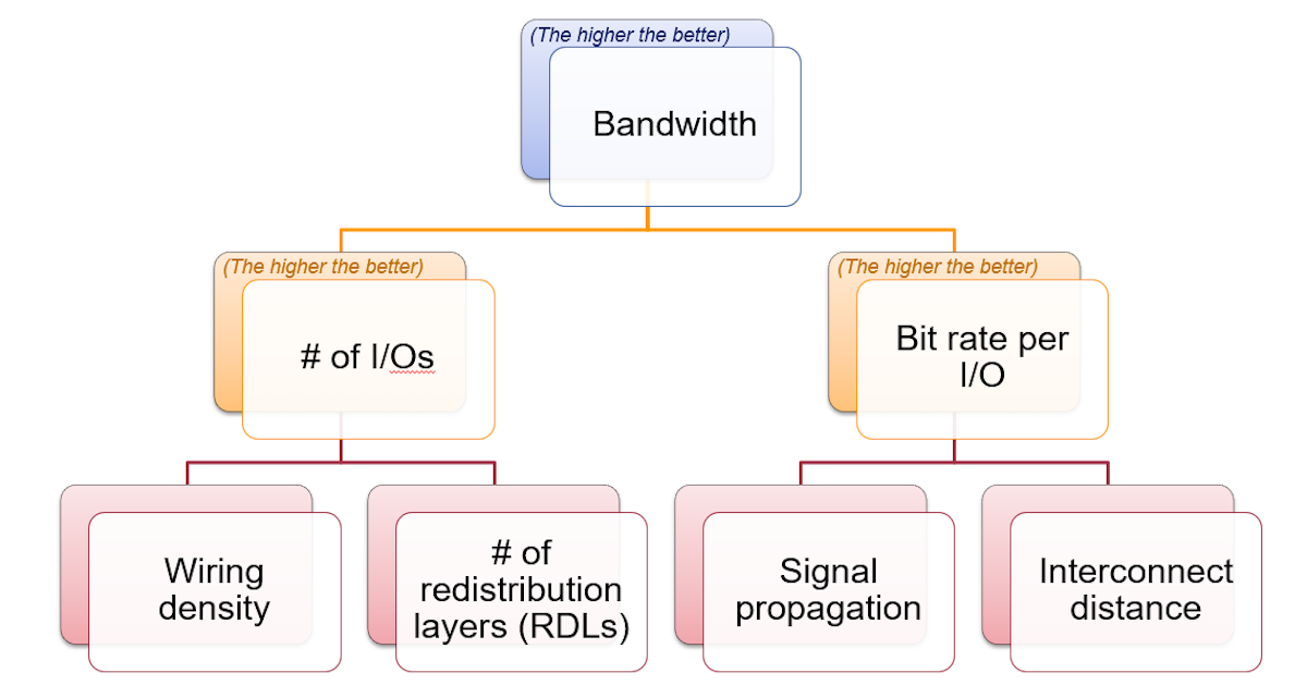
Key factors that affect the bandwidth of a packaged module. Source: IDTechEx
 
Unleashing High Bandwidth: Exploring Materials and Processing for Advanced Semiconductor Packaging
Delving deeper into achieving higher wiring density and a higher bit rate per I/O from a materials and processing perspective reveals the critical role played by the selection of dielectric materials and the utilization of appropriate processing techniques. These factors have a significant impact on the overall performance and capabilities of the packaging system.
 
Electronic interconnects: SiO2 vs Organic dielectric. Source: IDTechEx
 
Selecting suitable dielectric materials is crucial, considering properties like low dielectric constant, optimal CTE (as close to the CTE of Cu as possible), and favorable mechanical characteristics that ensure module reliability, such as Young's modulus and elongation. These choices enable higher data rates while preserving signal integrity and facilitating fine line/space features for increased wiring density.
 
In high-performance accelerators, such as GPUs, inorganic dielectrics like SiO2 have been extensively utilized to achieve ultra-fine line/space (L/S) features. Nevertheless, their use is limited in applications that demand high-speed connectivity due to their high RC delays. As an alternative, organic dielectrics have been proposed for their cost-effectiveness and ability to mitigate RC delays through their low dielectric constant. However, organic dielectrics present challenges, including high CTE, which can negatively impact the device reliability, and difficulties in scaling to fine L/S features.
 
In addition to selecting appropriate materials, the processing techniques employed during packaging fabrication play a crucial role in achieving a higher number of I/Os and improving the bit rate per I/O. The steps involved in 2.5D packaging processes, including lithography, CMP (Chemical Mechanical Planarization), etching processes, and the CMP and bonding processes in 3D Cu-Cu hybrid bonding, present challenges in achieving tighter routing and increased wiring density. IDTechEx provides detailed insights into how the choice of materials influences the fabrication processes, offering a comprehensive understanding of their impact on advanced semiconductor packaging.
 
What materials and technologies are covered in this report?
Scope of "Materials and Processing for Advanced Semiconductor Packaging 2024-2034". Source: IDTechEx
 
IDTechEx's "Materials and Processing for Advanced Semiconductor Packaging 2024-2034" report is divided into four main parts, offering a structured approach to understanding advanced semiconductor packaging. The first part provides a comprehensive introduction to the technologies, development trends, key applications, and ecosystem of advanced semiconductor packaging, providing readers with a solid overview knowledge. The second part focuses on 2.5D packaging processes, delving into crucial aspects including dielectric materials for RDL and Microvia, RDL fabrication techniques, and material selection for EMC and MUF. Each sub-section within this part presents a detailed analysis of process flows, technology benchmarks, player evaluations, and future trends, providing readers with comprehensive insights.
 
The report continues beyond the discussion of 2.5D packaging to the third part, which focuses on the innovative Cu-Cu hybrid bonding technology for 3D die stacking. This section provides valuable insights into the manufacturing process and offers guidance on material selection for optimal outcomes. It also showcases case studies highlighting the successful implementation of Cu-Cu hybrid bonding using both organic and inorganic dielectrics. Additionally, the report includes a 10-year market forecast for the Organic Dielectric Advanced Semiconductor Packaging Module, presented in the last chapter. This forecast encompasses unit and area metrics, providing industry with meaningful perspectives into anticipated market growth and trends for the next decade.


ページTOPに戻る


Table of Contents

1. EXECUTIVE SUMMARY AND CONCLUSIONS
1.1. Report scope
1.2. Advanced semiconductor packaging - An overview
1.3. From 1D to 3D semiconductor packaging
1.4. Semiconductor packaging - An overview of technology
1.5. Overview of interconnection technique in advanced semiconductor packaging
1.6. Key trends in fan-out packaging
1.7. Key factors to consider when choosing material for electronic interconnects
1.8. Key parameters for organic RDL materials for next generation 2.5D fan-out packaging
1.9. Benchmark of organic dielectrics for RDL
1.10. Industry players of organic RDL
1.11. Comparison of polymer dielectric materials in current high-performance packages
1.12. Benchmark of RDL formation technology
1.13. Overview of RDL L/S range by different RDL formation technology (1)
1.14. Overview of via diameter range by different microvia creation technology (1)
1.15. Overview of via diameter range by different microvia creation technology (2)
1.16. Overview of lithography challenges in high density RDL packaging
1.17. Key parameters for EMC materials
1.18. Challenges in conventional bumping
1.19. Micro bumps (µ bumps) vs bumpless Cu-Cu hybrid bonding
1.20. Overview of devices that make use of hybrid bonding
1.21. Cu-Cu hybrid bonding manufacturing process flow
1.22. 3D SoIC process flow deep dive - 1
1.23. Key factors in hybrid bonding that are impacted by the choice of dielectric material
1.24. Inorganic dielectric vs organic dielectric: A quick overview
1.25. Technology Benchmark of different dielectric materials for Cu-Cu hybrid bonding
1.26. Key process know-how for inorganic dielectric Cu-Cu hybrid bonding
1.27. Comparison of polymer case studies for hybrid bonding benchmarking
1.28. Key summary of polymer dielectric for hybrid bonding research
1.29. Forecast: Organic Dielectric Advanced Semiconductor Packaging Module Area (Unit and mm2)
2. INTRODUCTION OF ADVANCED SEMICONDUCTOR PACKAGING
2.1.1. Advanced semiconductor packaging - An overview
2.1.2. The rise of advanced semiconductor packaging and its challenges
2.1.3. From 1D to 3D semiconductor packaging
2.1.4. Semiconductor packaging - An overview of technology
2.1.5. Overview of interconnection technique in advanced semiconductor packaging
2.1.6. Fan out wafer level packaging
2.1.7. Interposer technology
2.1.8. 2.5D and 3D IC packaging
2.1.9. 2.5D IC Packaging
2.1.10. 2.5D IC packaging
2.1.11. 3D IC packaging technology
2.1.12. 3D IC packaging
2.1.13. 3D IC packaging
2.1.14. Advanced semiconductor packaging technologies - Our scope
2.1.15. Packaging trend for key markets
2.2. Advanced Semiconductor Packaging - Ecosystem
2.2.1. Business value chain in the IC industry
2.2.2. Ecosystem/Business model in the IC industry
2.2.3. Role and advantages of players in advanced semiconductor packaging market
2.2.4. Players in advanced semiconductor packaging and their solutions
2.2.5. An overview of chip supply chain
3. ADVANCED SEMICONDUCTOR PACKAGING: PERFORMANCE EVALUATION, AND ITS LINK TO FABRICATION PROCESSES AND MATERIALS
3.1.1. Key factors impacting advanced semiconductor packaging performance
3.1.2. Primary considerations for advanced packaging
3.1.3. The key metrics that impact advanced semiconductor packaging performance: Bandwidth
3.1.4. The definition of IO density
3.1.5. IO density calculation
3.1.6. Routes to increase I/O density
3.1.7. The key metrics that impact advanced semiconductor packaging performance: Power efficiency
3.2. 2.5D Packaging process flow know-how
3.2.1. 2.5D Packaging - High density fan-out packaging
3.2.2. Key trends in fan-out packaging
3.2.3. Fan-out packaging process overview
3.2.4. Fan-out chip-first process flow
3.2.5. Fan-out Chip-last process flow
3.2.6. Fan-out chip last RDL formation - Development trend
3.2.7. Challenges in future fan-out process
3.2.8. 2.5D Packaging that involves Si as electronic interconnect
3.2.9. Through-Si-Via (TSV) process flow
3.2.10. Dual Damascene process flow (for inorganic RDL fabrication)
3.2.11. Process flow for Si interposer on package substrate
3.3. Fan out process flows from key companies
3.3.1. SPIL FOEB Technology process flow
3.3.2. ASE FOCoS Process flow (1)
3.3.3. Flip chip on FOWLP - Process flow
3.3.4. Samsung's FOWLP device structure
3.4. Redistribution layer (RDL) & Microvia - Materials
3.4.1. Redistribution Layer (RDL)
3.4.2. Key Factors to Consider When Choosing material for Electronic Interconnects
3.4.3. Dielectric thickness of RDL
3.4.4. Electronic interconnects: SiO2 vs Organic dielectric
3.4.5. Limitations of SiO2 in 2.5D packaging
3.4.6. Electrical characteristics vs different RDL solution - Amkor's perspective
3.4.7. Replace inorganic dielectric with organic polymers?
3.4.8. Importance of low-loss RDL materials for different packaging technologies
3.4.9. Key parameters for organic RDL materials for next generation 2.5D fan-out packaging
3.4.10. Benchmark of organic dielectrics for RDL
3.4.11. Benchmark of material properties used in packaging
3.4.12. Dielectric challenges in fan-out applications - 1
3.4.13. Dielectric challenges in fan-out applications - 2
3.4.14. Industry players of organic RDL
3.4.15. RDL-dielectric suppliers: Toray's polyimide materials
3.4.16. Toray's solution for advanced semiconductor packaging
3.4.17. Low Dk and Low Df materials for RF devices - Solution from Toray
3.4.18. RDL-dielectric suppliers: HD Microsystems
3.4.19. Low-curing temp. RDL from HD Microsystem
3.4.20. RDL-dielectric suppliers: DuPont's Arylalkyl polymers (1)
3.4.21. RDL-dielectric suppliers: DuPont's PID dryfilm
3.4.22. RDL-dielectric suppliers: DuPont's InterVia
3.4.23. RDL-dielectric suppliers: Taiyo Ink's epoxy-based RDL
3.4.24. RDL-dielectric suppliers: Ajinomoto's nanofiller ABF
3.4.25. RDL-dielectric supplier: Showa Denko
3.4.26. Low-loss RDL materials for mmWave: TSMC's InFO AiP
3.4.27. Comparison of polymer dielectric materials in current high performance packages
3.5. Redistribution layer (RDL) & Microvia - Fabrication Processes
3.5.1. Overview of RDL fabrication technology
3.5.2. Semi-Additive Process (SAP) for RDL formation (organic dielectric)
3.5.3. Dual damascene process for RDL formation (organic dielectric)
3.5.4. Benchmark of RDL formation technology
3.5.5. Overview of RDL fabrication technologies
3.5.6. Benchmark of RDL formation technology (cont.)
3.5.7. Overview of RDL L/S range by different RDL formation technology (1)
3.5.8. Overview of microvia creation technology
3.5.9. Fine scale microvia creation technology - technology trend
3.5.10. Overview of via diameter range by different microvia creation technology (1)
3.5.11. Overview of via diameter range by different microvia creation technology (2)
3.5.12. Overview of lithography challenges in high density RDL packaging
3.5.13. Bottlenecks for <2/2 µm L/S RDL Scaling
3.5.14. Two key process considerations for below 2/2 µm L/S organic RDL
3.5.15. Cu dual damascene process for organic RDL formation - TSMC
3.5.16. Embedded Cu trace process - TSMC's high density fan-out package
3.5.17. How RDL affects transmission line loss?
3.5.18. Embedded trace RDL (ETR) process by Amkor (S-SWIFT package)
3.5.19. Embedded trace RDL (ETR) process for RDL formation
3.5.20. Embedded trace RDL (ETR) process for RDL formation
3.5.21. Summary: Organic RDL technology development trend - 1
3.5.22. Summary: Organic RDL technology development trend - 2
3.6. Temporary bonding and debonding
3.6.1. Mitsui Mining and Smelting Co. Ltd. Solution (1)
3.6.2. Mitsui Mining and Smelting Co. Ltd. Solution (2)
3.6.3. Mitsui Mining and Smelting Co. Ltd. Solution (3)
3.7. Epoxy molded compounds (EMC) and mold under fill (MUF)
3.7.1. What are EMC and MUFs?
3.7.2. Epoxy Molding Compound (EMC)
3.7.3. Key parameters for EMC materials
3.7.4. Importance of dielectric constant for EMC used in 5G applications
3.7.5. Experimental and commercial EMC products with low dielectric constant
3.7.6. Epoxy resin: Parameters of different resins and hardener systems
3.7.7. Fillers for EMC
3.7.8. EMC for warpage management
3.7.9. Supply chain for EMC materials
3.7.10. EMC innovation trends for high frequency applications
3.7.11. High warpage control EMC for FO-WLP
3.7.12. Possible solutions for warpage and die shift
3.7.13. EMC suppliers: Sumitomo Bakelite
3.7.14. EMC suppliers: Sumitomo Bakelite
3.7.15. EMC suppliers: Kyocera's EMCs for semiconductors
3.7.16. EMC suppliers: Samsung SDI
3.7.17. EMC suppliers: Showa Denko
3.7.18. EMC suppliers: Showa Denko's sulfur-free EMC
3.7.19. EMC suppliers: KCC Corporation
3.7.20. Molded underfill (MUF)
3.7.21. Liquid molding compound (LMC) for compression molding
4. CU-CU HYBRID BONDING TECHNOLOGY FOR 3D DIE STACKING
4.1.1. Challenges in conventional bumping
4.1.2. Micro bumps (µ bumps) vs bumpless Cu-Cu hybrid bonding
4.1.3. Bonding pitch size needs to scale with TSV development
4.1.4. Performance benchmark of devices based on micro bumps vs Cu-Cu bumpless hybrid bonding - 1
4.1.5. Commercial products that use bumpless Cu-Cu hybrid bonding
4.1.6. Overview of devices that make use of hybrid bonding
4.2. Cu-Cu hybrid bonding - Manufacturing processes
4.2.1. Three ways of Cu-Cu hybrid bonding
4.2.2. D2W (Die-to-Wafer) process
4.2.3. Cu-Cu hybrid bonding manufacturing process flow
4.2.4. Cu-Cu hybrid bonding - Process parameter
4.3. 3D SoIC manufacturing processes deep dive
4.3.1. 3D SoIC process flow deep dive - 1
4.3.2. 3D SoIC process flow deep dive - 2
4.3.3. 3D SoIC process flow deep dive - 3
4.3.4. 3D SoIC process flow deep dive - 4
4.3.5. Application examples of 3D SoIC packages
4.3.6. Key Applications of 3D SoIC packages
4.3.7. 3D SoIC process - A quick overview
4.3.8. Challenges in Cu-Cu hybrid bonding manufacturing process
4.4. Cu-Cu hybrid bonding - The choice of materials
4.4.1. Choices of dielectric materials for hybrid bonding
4.4.2. Key factors in hybrid bonding that are impacted by the choice of dielectric material
4.4.3. Challenges in using inorganic dielectric materials
4.4.4. Benefits of organic dielectric materials
4.4.5. Challenges of using organic dielectric materials
4.4.6. Inorganic dielectric vs organic dielectric: A quick overview
4.4.7. Technology Benchmark of different dielectric materials for Cu-Cu hybrid bonding
4.4.8. Polymer-based dielectric hybrid bonding
4.5. Cu-Cu hybrid bonding based on organic dielectric - Case studies
4.5.1. HD Microsystem 's polyimide solution for hybrid bonding - 1
4.5.2. HD Microsystem 's polyimide solution for hybrid bonding - 2
4.5.3. Showa Denko Copper/Polyimide hybrid bonding - 1
4.5.4. Showa Denko Copper/Polyimide hybrid bonding - 2
4.5.5. Cu/Polymer hybrid bonding simulation results from IME
4.5.6. Polyimide/Cu hybrid bonding materials characterization from Applied Materials & IME
4.5.7. Brewer Science - Photosensitive permanent bonding materials for polymer/Cu hybrid bonding - 1
4.5.8. Brewer Science - Photosensitive permanent bonding materials for polymer/Cu hybrid bonding - 2
4.5.9. Key summary of polymer dielectric for hybrid bonding research
4.5.10. Comparison of polymer case studies for hybrid bonding benchmarking
4.5.11. Benchmark of polymer used for hybrid bonding
4.5.12. Keys to select the right polymer for Cu-Cu hybrid bonding
4.5.13. List of inorganic fillers for CTE improvement in polymers
4.5.14. List of inorganic fillers for thermal conductivity improvement in polymers
4.6. Cu-Cu hybrid bonding based on inorganic dielectric
4.6.1. Samsung's Cu-Cu bonding
4.6.2. Cu-Cu hybrid bonding - Mitsubishi Heavy Industries Machine Tool
4.6.3. Improved Cu-Cu hybrid bonding through Cu enlargement - A study from Tohoku/T-Micro/JCU
4.6.4. 1 µm pitch Cu-Cu hybrid bonding base on SiCN - A study from imec
4.6.5. Self-Assembly for Hybrid Bonding - A study from CEA-Leti and Intel
4.6.6. SiO2 C2W Hybrid Bonding from IME
4.6.7. Die stacking from Xperi (Adeia)
4.6.8. XPERI(ADEIA) License map
4.6.9. TSMC hybrid bonding technology for AMD CPU
4.6.10. Stacking DRAMs using hybrid bonding - A study from SK Hynix
4.6.11. Sony's hybrid bonding - Recent development
4.6.12. Key process know-how for inorganic dielectric Cu-Cu hybrid bonding
4.6.13. Cu/Sn-Cu/Sn hybrid bonding
5. MARKET FORECAST
5.1. Forecast: Organic Dielectric Advanced Semiconductor Packaging Module Area (Unit and mm2)
5.2. Forecast: Organic Dielectric Advanced Semiconductor Packaging Module (Unit)
5.3. Forecast: Organic Dielectric Advanced Semiconductor Packaging Module Area (mm2)
5.4. Company profiles


ページTOPに戻る

ご注文は、お電話またはWEBから承ります。お見積もりの作成もお気軽にご相談ください。

webからのご注文・お問合せはこちらのフォームから承ります

本レポートと同分野の最新刊レポート

  • 本レポートと同分野の最新刊レポートはありません。

本レポートと同じKEY WORD()の最新刊レポート

  • 本レポートと同じKEY WORDの最新刊レポートはありません。

よくあるご質問


IDTechEx社はどのような調査会社ですか?


IDTechExはセンサ技術や3D印刷、電気自動車などの先端技術・材料市場を対象に広範かつ詳細な調査を行っています。データリソースはIDTechExの調査レポートおよび委託調査(個別調査)を取り扱う日... もっと見る


調査レポートの納品までの日数はどの程度ですか?


在庫のあるものは速納となりますが、平均的には 3-4日と見て下さい。
但し、一部の調査レポートでは、発注を受けた段階で内容更新をして納品をする場合もあります。
発注をする前のお問合せをお願いします。


注文の手続きはどのようになっていますか?


1)お客様からの御問い合わせをいただきます。
2)見積書やサンプルの提示をいたします。
3)お客様指定、もしくは弊社の発注書をメール添付にて発送してください。
4)データリソース社からレポート発行元の調査会社へ納品手配します。
5) 調査会社からお客様へ納品されます。最近は、pdfにてのメール納品が大半です。


お支払方法の方法はどのようになっていますか?


納品と同時にデータリソース社よりお客様へ請求書(必要に応じて納品書も)を発送いたします。
お客様よりデータリソース社へ(通常は円払い)の御振り込みをお願いします。
請求書は、納品日の日付で発行しますので、翌月最終営業日までの当社指定口座への振込みをお願いします。振込み手数料は御社負担にてお願いします。
お客様の御支払い条件が60日以上の場合は御相談ください。
尚、初めてのお取引先や個人の場合、前払いをお願いすることもあります。ご了承のほど、お願いします。


データリソース社はどのような会社ですか?


当社は、世界各国の主要調査会社・レポート出版社と提携し、世界各国の市場調査レポートや技術動向レポートなどを日本国内の企業・公官庁及び教育研究機関に提供しております。
世界各国の「市場・技術・法規制などの」実情を調査・収集される時には、データリソース社にご相談ください。
お客様の御要望にあったデータや情報を抽出する為のレポート紹介や調査のアドバイスも致します。


詳細検索

このレポートへのお問合せ

03-3582-2531

電話お問合せもお気軽に


2024/07/01 10:26

162.23 円

174.76 円

207.97 円

ページTOPに戻る